General Dimensional Tolerances For Sheet Metal Formed Parts

Engineering Drawings Gd T For The Quality Engineer Mechanical Engineering Design Mechanical Engineering Engineering Symbols

Engineering Drawings Gd T For The Quality Engineer Mechanical Engineering Design Mechanical Engineering Engineering Symbols

Iso 2768 General Geometrical Tolerances And Technical Drawings Plianced Inc

Iso 2768 General Geometrical Tolerances And Technical Drawings Plianced Inc

Sheet Metal Bending Tolerances

Sheet Metal Bending Tolerances

Pdf Tolerance Transfer In Sheet Metal Forming

Pdf Tolerance Transfer In Sheet Metal Forming

Gd T 101 An Introduction To Geometric Dimensioning And Tolerancing Fictiv Hardware Guide

Gd T 101 An Introduction To Geometric Dimensioning And Tolerancing Fictiv Hardware Guide

The Vector Stencils Library Dimensioning And Tolerancing Contains 45 Symbols Of Geometric Dimensions Geometric Tolerancing Geometric Symbols Design Elements

The Vector Stencils Library Dimensioning And Tolerancing Contains 45 Symbols Of Geometric Dimensions Geometric Tolerancing Geometric Symbols Design Elements

The Vector Stencils Library Dimensioning And Tolerancing Contains 45 Symbols Of Geometric Dimensions Geometric Tolerancing Geometric Symbols Design Elements

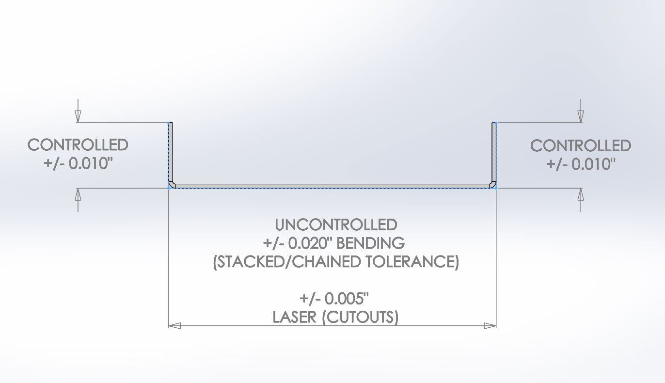
1 all manufacturing tolerances used up to that point such as laser cutting tolerances welding tolerances and more 2 all bend tolerances for the entire part added together we call this an uncontrolled dimensions because there are additional tolerances to consider.

General dimensional tolerances for sheet metal formed parts.

This japanese industrial standard specifies general dimensional tolerances for parts formed by press working from sheet metal. Furthermore the parts formed by press working from sheet metal mean those which have been formed by press working of punching bending and drawing from sheet metal and do not include those formed by shear working from sheet metal. Tolerance for length of chamfered portion. Protocase commits to supply parts to the dimensional tolerances noted in this resource unless we have agreed to other tolerances when quoting your job.

However on the sketches i was given the inside width of the u is specified possibly because the inside surfaces will mate with another part. Sms is not responsible for distortion of internal features inside bend areas applies to all internal features applies to flat part length up to 24 00. This part is intended to simplify drawing indications and specifies general tolerances in four tolerance classes. General dimensional tolerance of blanking unit mm 1.

General dimensional tolerances for parts formed excerpt from jis b 0408 0410 1991 general dimensional tolerance exce rpt f om jis b 045 19 by press working from sheet metal and shear from metal plates technical data technical data table 1. As per design requirements and manufacturing capability tolerance class is defined. It applies to the dimensions of work pieces that are produced by metal removal or are formed from sheet metal. As a designer if you carefully consider the manufacturer s tolerances when designing you will have a greater outcome than simply designing and assuming all parts are nominal size.

Flat part length over 24 00 tolerance is 0 010 k l a sheet 1 of 1 sms sheet metal tolerances do not scale drawing. And for machined components iso 27 68 fh can be used. Regular cut dimension tolerance jis b 0405 1991 tolerances for length excluding chamfered portion units. Uncontrolled dimensions contain two different categories of tolerances.

General tolerance iso 2768 does not specify where to use these tolerances. Dimensional tolerances only apply to part in constrained state 3. For sheet metal parts iso 27 68 mk is used. I know the standard is to dimension the outside of the part along with the inside radii.

General dimensional tolerances for parts formed. General dimensional tolerances for parts formed by press excerpts from jis b 0408 1991 working from sheet metal and shear from metal plates jis b 0410 1991 technical data 1. Tolerances for linear and angular dimensions without individual tolerance indications.

Gd T Symbols Mechanical Engineering Design Mechanical Design Geometric Tolerancing

Gd T Symbols Mechanical Engineering Design Mechanical Design Geometric Tolerancing

Sheet Metal Design Guide Geomiq

Sheet Metal Design Guide Geomiq

Geometric Tolerances Investment Castings To Precise Geometric Tolerances Milwaukee Precision Geometric Tolerancing Geometric Mechanical Engineering Design

Geometric Tolerances Investment Castings To Precise Geometric Tolerances Milwaukee Precision Geometric Tolerancing Geometric Mechanical Engineering Design

Gd T Symbols Reference Guide From Sigmetrix Engineering Symbols Mechanical Design Mechanical Engineering Design

Gd T Symbols Reference Guide From Sigmetrix Engineering Symbols Mechanical Design Mechanical Engineering Design

Source : pinterest.com